



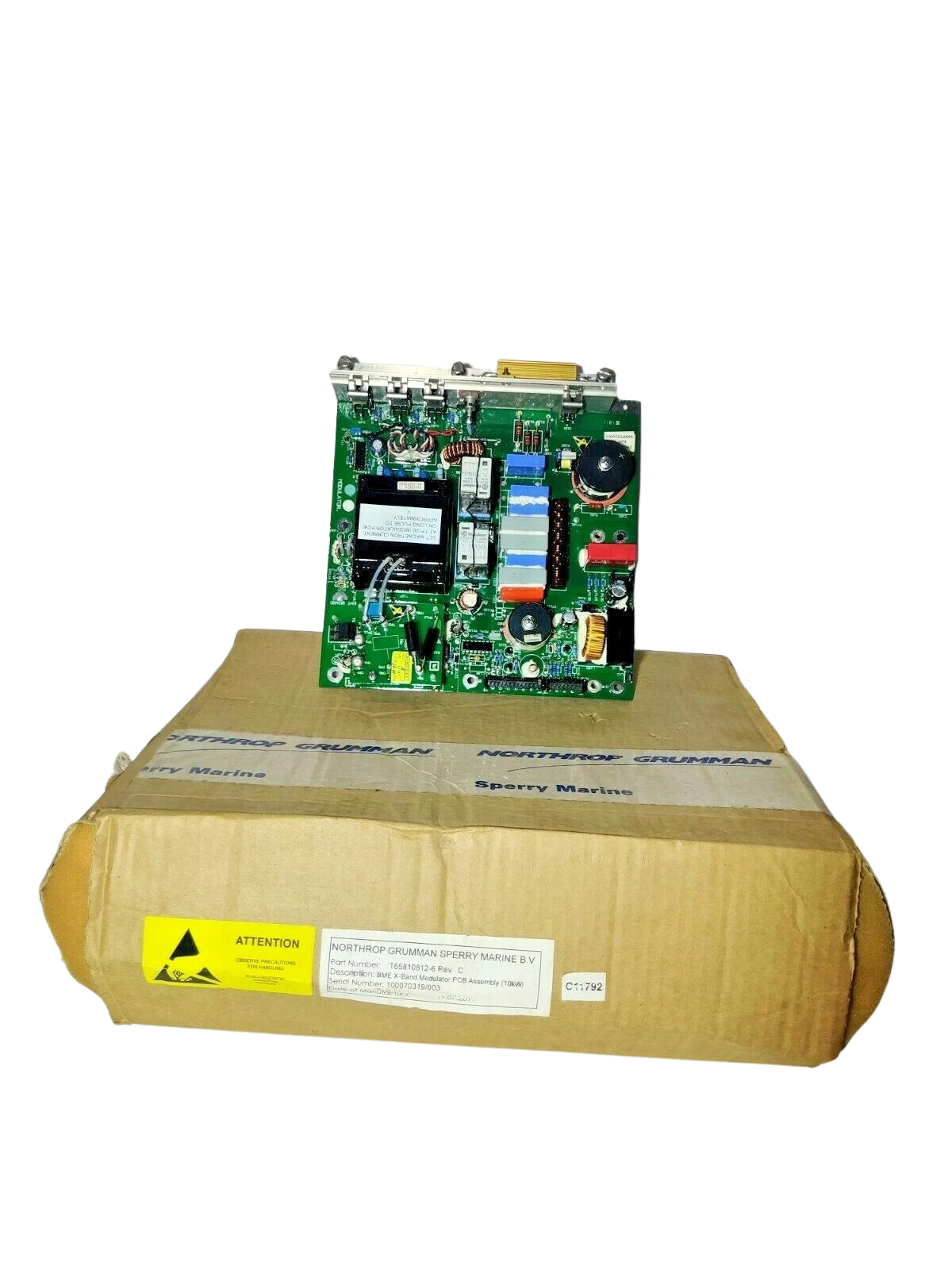
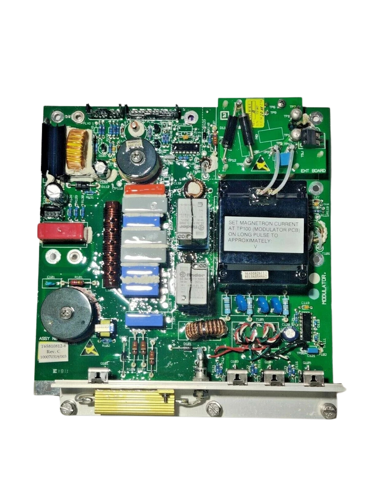
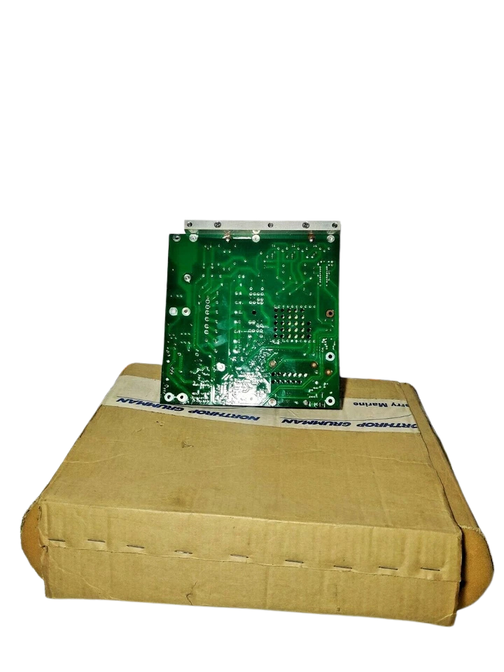


Sperry Marine T65810812-6 Rev C 10KW Modulator PCB
Condition: New – Open Box

Sperry Marine T65810812-6 Rev C Modulator PCB ASSY 10KW
The Sperry Marine T65810812-6 Rev C Modulator PCB ASSY is a vital, high precision electronic component for exclusive use with Northrop Grumman Sperry Marine 10kW X-Band commercial radar transceivers. This assembly is the main pulse generation control center, it controls the output signal of the radar transmitter to drive the magnetron under tight pulse repetition frequencies (PRF).
The primary operational function of the T65810812-6 assembly is the generation of a precise 8kV, 8A negative pulse directed to the cathode of the magnetron. It leverages a silicon-controlled rectifier (SCR) network to resonantly charge the internal Pulse Forming Network (PFN) – 1200V derived from the transceiver’s primary – 600V Modulator High Tension (HT) rails. Discharge timing is managed by a series array of three Insulated Gate Bipolar Transistors (IGBTs) through a step-up pulse transformer featuring a high-efficiency 12:1 turns ratio. This creates sharp, clean pulse edges crucial for high-resolution target detection in adverse marine environments.
Model Details:
- Model Designation: T65810812-6 Modulator PCB Assembly
- Manufacturer Part Number (MPN): T65810812-6 (Revision C)
- Associated Sub-Assembly Numbers: 65810812-6 / 65801816-1 Rev A
- Power Rating: 10 kW Peak Pulse Power Output
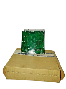
Technical Specifications: Sperry Marine T65810812-6
| Parameter / Metric | Technical Value / Specification |
|---|---|
| Nominal Output Voltage Pulse | -8.0 kV DC (Negative-going pulse at Magnetron Cathode) |
| Peak Pulse Current Output | 8.0 A (Amperes peak nominal) |
| PFN Charge Potential | Resonantly charged to -1200V DC via input rail SCR |
| Input High Tension (HT) Voltage | -600V DC Modulator Supply Input Rail |
| Pulse Transformer Configuration | Heavy-duty toroidal core, 12:1 voltage step-up ratio |
| Switching Element Architecture | 3x High-Voltage Series Insulated Gate Bipolar Transistors (IGBT) |
| Pulse Selection Control | Electromechanical relays triggered by logic-level Pulse Length Control Lines |
| Fall Time Optimization | On-board Saturable Reactor across primary windings for short/medium pulse sharpening |
| Printed Circuit Board Substrate | FR-4 glass-reinforced epoxy, multi-layer, conformal coated for marine deployment |
| Operating Frequency Band | X-Band Navigation Frequency Spectrum (approx. 9410 MHz) |
Features
- Advanced Resonant PFN Charging: High reliability SCR system powers the Pulse Forming Network to 1200t V fast for reliable pulse power.
- Triple-IGBT discharge switching: it uses three series-connected Insulated Gate Bipolar Transistors for fast discharge switching with low thermal dissipation.
- Dynamic pulse length management: Onboard relays are connected to the pulse length control lines, enabling dynamic addition or isolation of parts of the PFN for short, medium and long-range radar pulses.
- Ruggedized Marine Form Factor: Coated with moisture-resistant conformal insulation to reduce the impact of high-humidity and high-salinity marine settings.
Applications
- Bridge Radar Maintenance: Direct drop-in repair of broken or degraded modulator portions in commercial marine radar systems.
- Deep-Sea Vessels: Essential inventory spares for long-range cargo vessels, tankers and passenger ships equipped with Bridge Master E (BME) series radar systems.
- Transceiver Overhauls: Replaced core electronic module during standard 5 year class-survey overhauls of 10 kW X-band scanner machines.
Part Number Cross-References
- T65810812-6 (Base Part Number)
- T65810812-6 Rev B (Preceding Version)
- 5810812-6 Rev C (Current Version)
Installation & Commissioning Pro Tips:
- Pulse Length Relay Verification: When replacing a Rev B card with a Rev C board in older systems, the PFN selection relays must be cycled before High Tension is applied. Run the offline diagnostics sequence via the radar command console. Check the pulse length control line logic for smooth transition from short to long pulse widths.
- Saturable Reactor inspect If you receive poor targets at short ranges right after installation, inspect the transient responses around the rear edge of the brief pulse. You may need to make a little adjustment or replacement of the main load clamp/saturable reactor line connectors to reduce tailing.
- Avoid Conformal Damage DO NOT touch the board components with bare hands. Over time, small leakage channels can form at high voltage from salt deposits left by skin contact which can cause intermittent PRF jitter or premature arc problems within the transceiver chassis. Handle the PCB only by structural edges using clean, dry, anti-static gloves.