



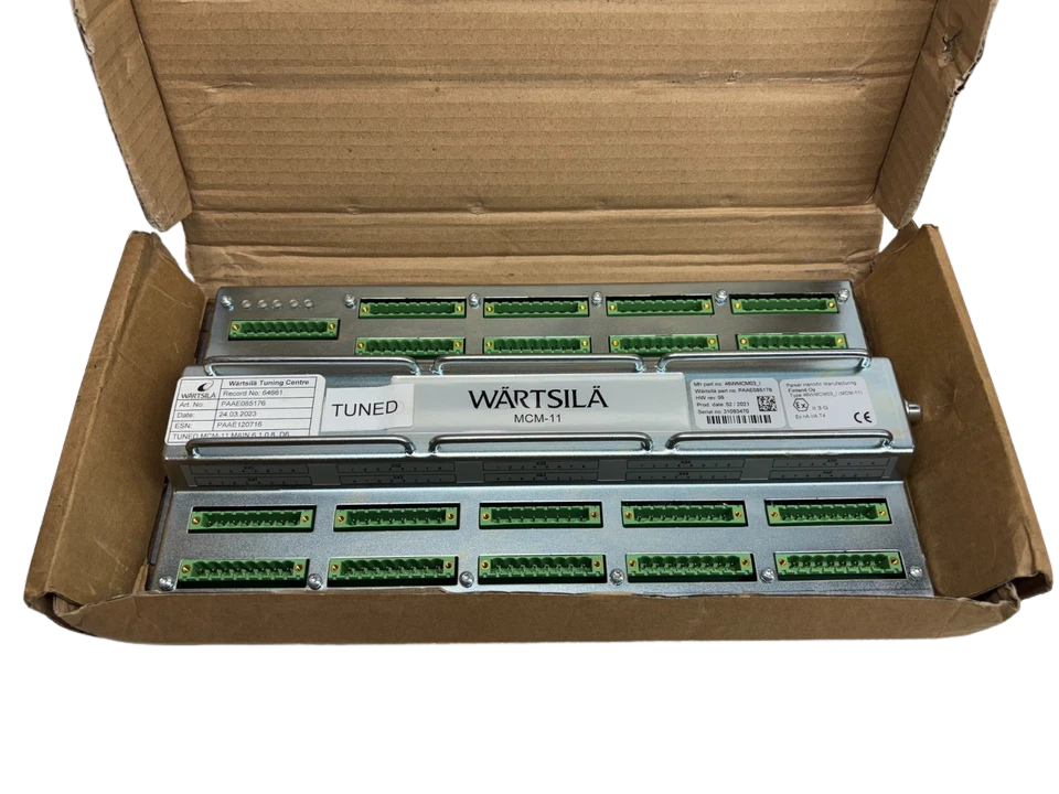
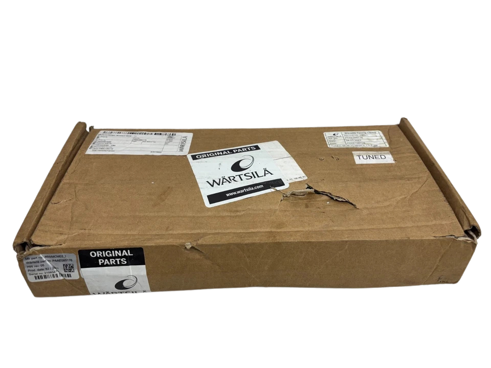
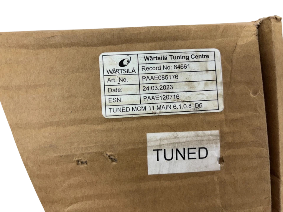
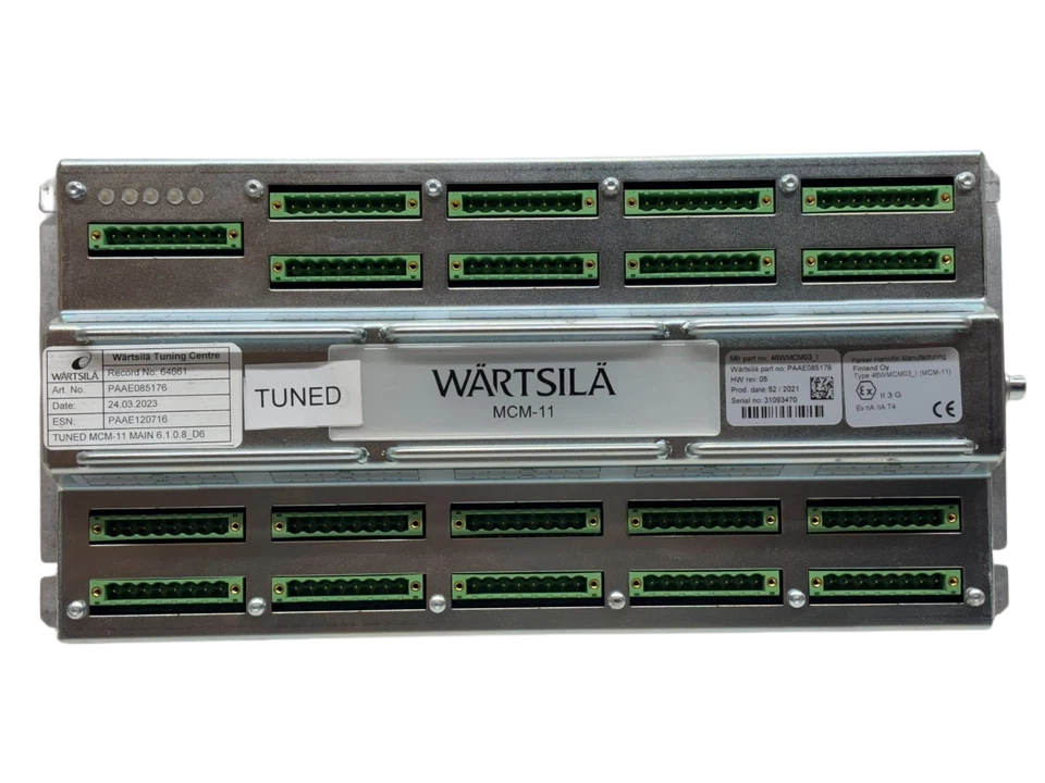
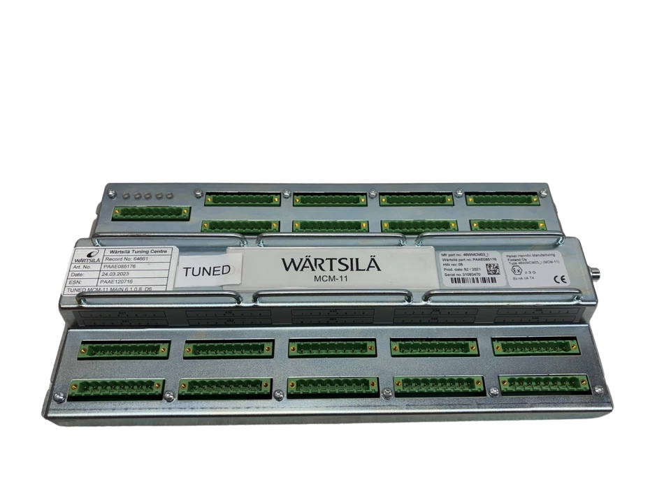
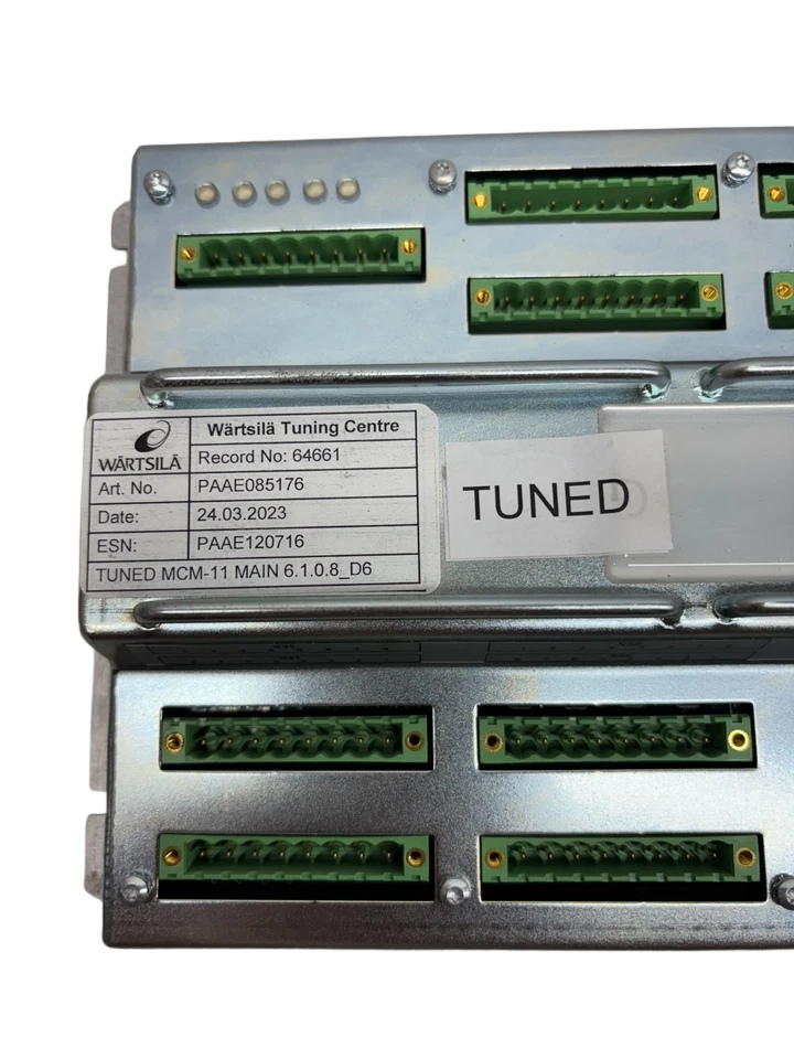
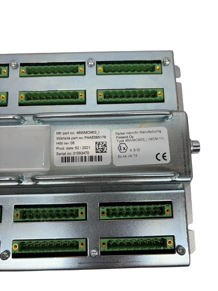
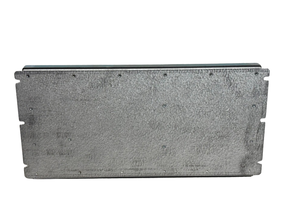




Wartsila MCM-11 Main Control Module 46WMCM03_I
The Wartsila MCM-11 Main Control Module (MPN: 46WMCM03_I / PAAE085179) is an engine-mounted, microprocessor-driven control unit engineered for Wärtsilä medium-speed marine diesel and dual-fuel propulsion engines as well as auxiliary generating sets. As a central computational and I/O node within the Wärtsilä engine control architecture (including UNIC automation topologies), the MCM-11 executes real-time speed governing, fuel rack/actuator positioning, start/stop logic sequencing, cylinder synchronization, safety trips, and bidirectional communication over redundant industrial fieldbuses.
Constructed inside a shock-rated, cast-aluminum/sheet-steel enclosure with conformal-coated industrial PCBs, the MCM-11 operates directly within engine-room ambient conditions. It handles severe mechanical vibration, high thermal gradients, and electromagnetic interference (EMI) originating from high-voltage switchboards and variable-frequency motor drives. High-density spring-cage/screw pluggable terminal connectors provide reliable signal integrity under constant marine engine vibration spectra.
Model Details
- Manufacturer: Wärtsilä Corporation
- Module Type: MCM-11 (Main Control Module)
- Hardware Model / Assembly Code: 46WMCM03_I (46WMCM03 Revision I / Rev 03)
- Wärtsilä Part Number (MPN): PAAE085179
- Internal Reference Designations: 46WMCM_I REV 03 / FKM4836V1
Technical Specifications: Wartsila MCM-11 (46WMCM03_I)
| Parameter / Subsystem | Engineering Specification | Operational Parameters & Tolerances |
|---|---|---|
| Nominal Supply Voltage | 24 V DC (Redundant Dual Feeds: PWR A & PWR B) | Operating range: 18 V DC to 32 V DC (9–36 V DC operational surge boundary, reverse-polarity protected) |
| Power Consumption | Typical: 15 W – 25 W | Max continuous load: 45 W with all digital active outputs and sensor power loops energized |
| Microprocessor Architecture | 32-bit Embedded Industrial RISC Engine | Non-volatile Flash memory for core firmware; battery-backed/FRAM for parameter calibration logs |
| Analog Inputs (AI) | Configurable 4–20 mA current loops & 0–10 V DC | 12-bit to 16-bit resolution; internal precision burden resistors (250 Ω); sensor fault/wire-break detection |
| Temperature Sensor Inputs | Dedicated RTD (Pt100) channels | 2-wire and 3-wire linearization; range: -50 °C to +600 °C (exhaust, cooling water, main bearing oil monitoring) |
| Digital / Binary Inputs (DI) | Optocoupled Isolated Inputs (24 V DC sink/source) | Input filter time constant: 1 ms to 20 ms configurable; galvanically isolated up to 1.5 kV DC |
| Speed / Frequency Pick-up | Dual Pick-Up Engine Speed Interfaces (MPU / Hall) | Magnetic pick-up 0.5 V–30 V RMS; frequency detection up to 15 kHz (flywheel gear tooth pulse detection) |
| Digital / Transistor Outputs (DO) | High-side Solid-State Switching (24 V DC) | Rated up to 2.0 A continuous per channel; short-circuit, thermal overload, and inductive kickback clamped |
| Relay Outputs (RO) | Potential-free changeover contacts (SPDT / Form C) | Contact rating: 250 V AC @ 2 A / 30 V DC @ 3 A (used for trip triggers, pre-alarms, common fault loops) |
| Actuator Control Output | PWM & Bipolar ±200 mA / 4–20 mA current drivers | Direct closed-loop positioning drive for electro-hydraulic fuel actuators and electronic governing linkages |
| Serial & Fieldbus Interfaces | CANopen / DeviceNet (Dual Isolated CAN channels) | Redundant engine network protocol, transfer speed: up to 500 kbps, 120 Ω bus termination jumperable |
| Auxiliary Communication | RS-485 / RS-422 Serial Ports (Modbus RTU) | Baud rates: 9600 to 115200 bps; interface terminals: GND / 485-A / 485-B; connects to AMS and local bridge display |
| Operating Ambient Temperature | -25 °C to +70 °C (-13 °F to +158 °F) | Direct engine-mounted and local operating panel (LOP) cabinet rated |
| Ingress Protection Rating | IP20 (Terminal level) / IP44/IP54 (when housed in cabinet) | Conformal coated circuit boards (MIL-I-46058C / IPC-CC-830 certified moisture & salt spray resistance) |
| Vibration & Shock Tolerance | IEC 60068-2-6 (2.0G to 4.0G acceleration) | Vibration sweep 3 Hz to 100 Hz at high mechanical stress levels conforming to IACS E10 engine installation rules |
Features
- Real-Time Deterministic Engine Governing: Houses high-speed RISC processing capable of running closed-loop fuel injection and rack control cycles within sub-millisecond execution windows, preventing rotational hunting during abrupt switchboard generator loading.
- Dual-Channel Galvanic Isolation: Every fieldbus channel (CANopen, Modbus RS-485), power input feed, and digital input circuit is galvanically decoupled to prevent ground-loop cross-talk and preserve mainboard operation during electrical ground faults.
- Redundant System Architectures: Direct hardware support for dual 24 V DC power supplies and dual isolated CAN fieldbus lines ensures continuous, bumpless control during single-point supply breaks or wiring integrity drops.
- Marine Ruggedized PCB Assembly: Coated in high-grade dielectric conformal lacquer to prevent bridge formation, dendritic short circuits, and trace corrosion caused by high-humidity, high-salinity ambient air in vessel machinery spaces.
- Integrated Hardware Diagnostics: Built-in surface LED arrays and register-level flags monitor watchdog statuses, sensor open/short circuits, line degradation, actuator feedback failure, and network timing errors in real time.
Compatibility
- Wärtsilä Medium-Speed Marine Engines:
- Wärtsilä 20 / 20DF
- Wärtsilä 26
- Wärtsilä 32 / 32DF
- Wärtsilä 34DF / 34SG
- Wärtsilä 38 / 38B
- Wärtsilä 46 / 46F / 46DF
- Wärtsilä 50DF
- Associated Automation Platforms:
- Wärtsilä UNIC Engine Control Systems (UNIC-C1, UNIC-C2, UNIC-C3)
- Wärtsilä WIP-11 Instrumentation / Operator Panels
- Power Distribution Modules (PDM-20 series)
- Relay Driver Modules (RM-10, RM-11A series)
- Compatible Downstream Plant & Systems:
- Marine Alarm and Monitoring Systems (AMS) via Modbus RTU / CANopen
- Integrated Automation Systems (IAS) from Kongsberg (K-Chief / AutoChief), SAM Electronics, Valmet DNA, and Nabtesco
Frequently Asked Questions
Can the Wartsila MCM-11 46WMCM03_I be installed directly without software loading?
No. While the MCM-11 hardware variant (46WMCM03_I) contains the base bootloader and kernel hardware drivers, the operational parameter maps—including cylinder counts, firing sequences, speed PID algorithms, and alarm limits—must be uploaded using the authorized engine service interface tool tailored to your engine serial number.
What are the earliest indications that an MCM-11 module is failing in service?
Common failure symptoms include intermittent CAN communication errors on the automation line, erratic speed signal dropouts triggering false overspeed warnings, unstable governor fuel-rack positioning during load changes, or failure of the internal watchdog relay to close upon 24 V DC power cycling.
How do I verify if the CAN bus terminating resistor is enabled on this module?
The module features internal termination selection pins/jumpers adjacent to the communication header block. Using a digital multimeter with the module powered down and communication harness unplugged, measure resistance across terminals CAN_H and CAN_L. A standalone terminated module will read approximately 120 Ω; unselected modules will read high impedance (several kilo-ohms).
What is the correct procedure for handling redundant 24 V DC power supplies on the MCM-11?
The module features dual independent power input terminals (Feed A and Feed B) with internal auctioneering/diode-ORing circuitry. Both inputs should be supplied from separated, isolated UPS or battery-backed DC power distribution buses. Ensure the potential difference between the ground points of Feed A and Feed B does not exceed 0.5 V DC to avoid ground equalizing currents.
Can a damaged terminal connector plug be replaced without swapping the entire unit?
Yes. The terminal blocks on the MCM-11 are modular, high-retention plug-in connectors. If a screw strips or a retaining clip cracks due to maintenance stress, individual terminal plugs can be unseated and replaced without replacing the main control module. Ensure all pins are dry and corrosion-free before re-seating.