


Blog
Sourcing Ship Alarm Monitoring System Parts: A Marine Engineer’s Guide

Sourcing Ship Alarm Monitoring System Parts: The Marine Engineer’s Technical Guide to Avoiding Engine Room Downtime
Ask any Chief Engineer or Electrical Technical Officer (ETO) what keeps them up at night during a deep-sea voyage, and they won’t say heavy weather. They will say a ghost fault in the Alarm Monitoring System (AMS).
The AMS is the nervous system of the vessel. It continuously processes thousands of data points from the main engine, auxiliary generators, pumps, and auxiliary systems. When a component within this network fails, you aren’t just losing visibility—you risk catastrophic mechanical failure or a major class non-conformity during a port state control inspection.
Sourcing the right ship alarm monitoring system parts requires a deep understanding of how these hardware layers interact, where they fail, and how to spot ruggedized, class-approved replacements that survive the extreme thermal and vibrational stresses of a modern engine room.
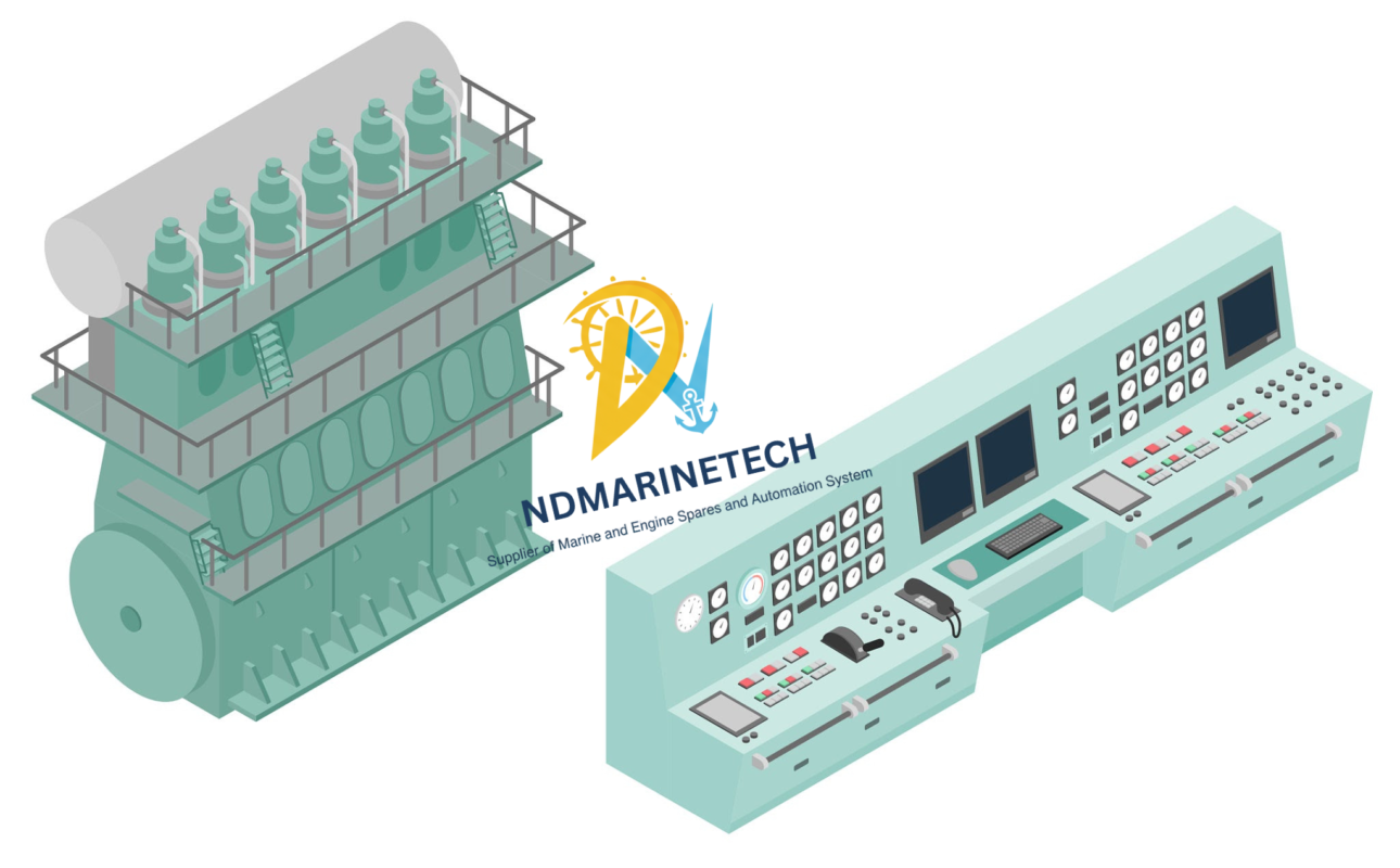
Anatomy of a Marine AMS Core
A marine alarm monitoring system consists of three separate hardware layers. If an alarm drops out or shows irregular data, it is nearly always possible to trace it down to one of these main categories of parts:
1) Sensor & Transmitter Layer (The Frontline)
These parts are in direct contact with the machinery and constantly exposed to vibration, oil spray and temperatures easily exceeding 50°C.
- Pressure Transmitters and Switches: These devices convert physical pressure (lubricating oil, jacket cooling water, fuel oil lines) into a standard electrical signal (usually 4-20mA analog current loop).
- Temperature sensors (RTDs and thermocouples) High-grade Pt100 or Pt1000 sensors are used to monitor exhaust gas temperatures, main bearings and alternator windings.
- Level Switches: Float or ultrasonic sensors to measure bilge, expansion tank and fuel day tank levels.
2) The Brains – The Data Acquisition & Processing Layer
This layer collects the raw sensor data which is located in the engine control room (ECR) panels or local starter boxes.
- I/O Modules convert the analog or digital signals from the sensors into clean digital data packets. If one channel burns out from a voltage spike, the whole module often has to be swapped out.
- System software runs in these core logic processing devices calledProgrammable Logic Controllers (PLCs) & Central Processors. They do the Boolean logic (ie, IF jacket water temperature > 92°C AND engine load > 50%, THEN trigger shutdown).
3) Human Machine Interface (HMI) and Display Layer
This is what the watchkeeping engineer actually sees on the bridge, and at the ECR.
- Marine Operator Panels & HMI Displays: Rugged touchscreen or keypad monitors intended to withstand voltage fluctuations and glare.
- Buzzer & Flash Warning Modules Audible alarms and extension system boxes in engineering cabins to ensure compliance with Unattended Machinery Space (UMS) notations.
High-Failure Parts: Diagnostics & Replacement Benchmarks
| Component Group | Common Failure Symptoms | Primary Root Cause | Corrective Sourcing Action |
|---|---|---|---|
| Pressure Transmitters | Signal freeze, fluctuating readings, “Open Loop” error. | Diaphragm fatigue from pressure pulsations; moisture ingress into the electrical connection. | Source heavy-duty sensors with high IP ratings (IP67 minimum) and built-in pulse dampeners. |
| I/O Communication Cards | Multiple sequential sensor channels failing simultaneously. | Thermal degradation of internal optocouplers; marine grounding faults causing back-EMF. | Opt for modular cards that allow hot-swapping without shutting down the entire rack. |
| HMI Operator Panels | Unresponsive touch matrices, screen flickering, fading CCFL/LED backlights. | Long-term exposure to engine room heat; continuous cycling of internal capacitors. | Ensure the replacement panel matches the exact firmware revision and communication protocol (Modbus, Profibus, NMEA). |
| System Power Supplies | Intermittent whole-system reboots during generator changeovers. | Dried-out electrolytic capacitors failing to smooth out DC voltage ripples. | Replace standard industrial units with dual-redundant, marine class-certified 24V DC power modules. |
Engineer’s Note On Grounding: Over 40% of automation panel “failures” are the result of stray currents and poor hull grounding. Before you chuck in an expensive I/O module, check with a high-impedance multimeter to see if there is insulation breakdown between the sensor shielding and the vessel steel structure.
Key Points to Consider When Buying Marine Automation Parts
It’s not as straightforward as ordering typical industrial electronics to get the right pieces for your monitoring matrix. The parts are not industrial grade . The internal components are not hardened to tolerate the filthy power grids and constant harmonic vibrations of commercial ships .
Safety and dependability of the system is of utmost importance and these metrics should be on top of your purchase checklist:
- Marine Class Approval: All important processors, power supply and safety-interlock components must be Type Approved by leading classification organizations such as DNV, ABS, Lloyd’s Register (LRS) or Bureau Veritas (BV). Without these your vessel could suffer serious compliance penalties.
- Firmware and Protocol Compatibility: If your modules depend on software (CPUs, network gateways, etc.) be sure that new hardware speaks the same communication protocol as your existing setup—Modbus RTU, CANbus, Profinet, or whatever your installation uses.
- Environmental Toughness: Always verify the operational specs. Engine room electronics require a wide operating temperature range (typically within enclosed steel panels up to 55°C or 70°C) and a robust electromagnetic compatibility (EMC) shielding.
The best protection against sudden automation failures is to have a good stock of critical I/O cards, pre-calibrated 4-20mA transmitters and clean power modules. Work with specialized maritime wholesalers who understand class requirements, technical cross-referencing and fast worldwide export logistics to keep your fleet operating safely, efficiently and fully compliant.
Related Integration Spares: Fire & Gas Detection Systems
Because modern ship alarm monitoring system networks integrate directly with fire safety panels and safety-interlock loops via Modbus and digital I/O networks, maintaining drop-in sensor spares is critical for total engine room coverage.
- Apollo Orbis Marine Optical Smoke Detector (ORB-OP-42001-MAR)
- Application: Reliable, class-approved smoke detection designed to minimize false alarms in high-vibration engine room spaces.
- [Request an RFQ / Check Global Stock]
- Marine Conventional Heat Detector (Rate-of-Rise)
- Application: Ideal for galley spaces and purifier rooms where ambient smoke is common but sudden temperature spikes indicate immediate danger.
- [Request an RFQ / Check Global Stock]
- Enclosed Marine Fire Alarm Control Panel Extension Modules
- Application: Relay output cards and buzzer modules to extend audible and visual alarms to engineer cabins for UMS compliance.
- [Request an RFQ / Check Global Stock]
- Fixed Engine Room Gas Detection Sensor Heads
- Application: Pre-calibrated replacement heads for detecting combustible fuel vapor leaks or low-oxygen hazards in enclosed machinery areas.
- [Request an RFQ / Check Global Stock]