



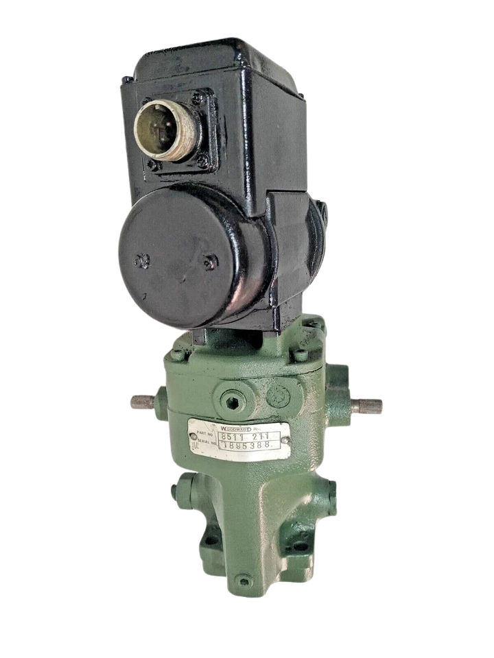
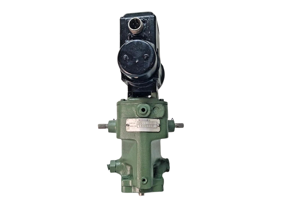
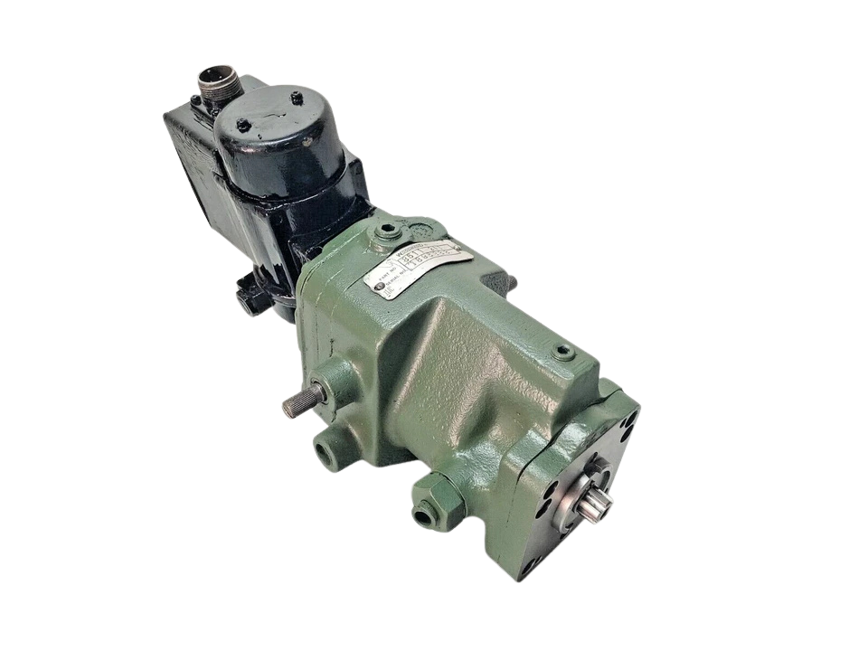
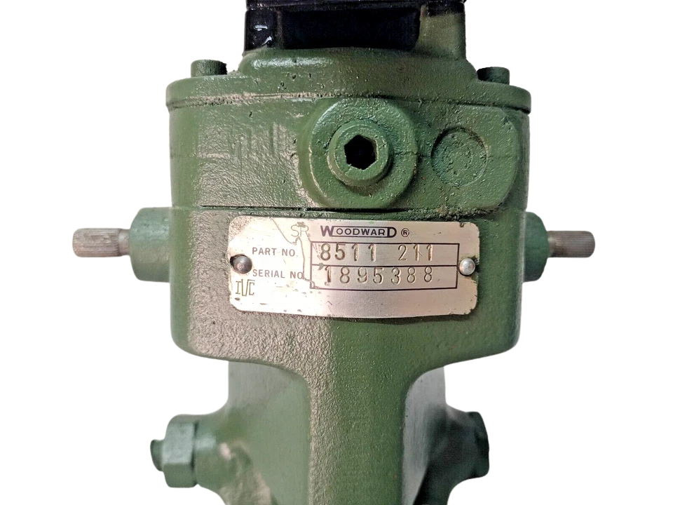
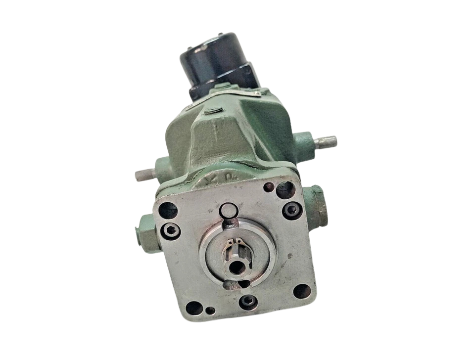
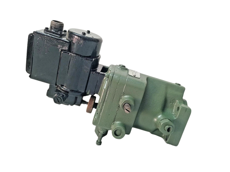
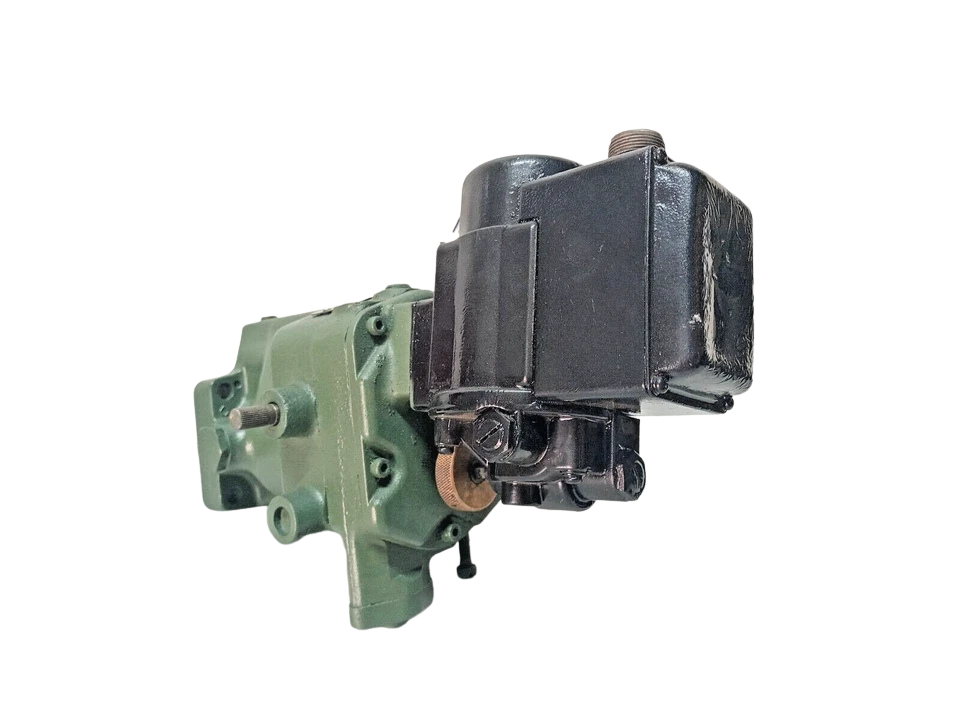
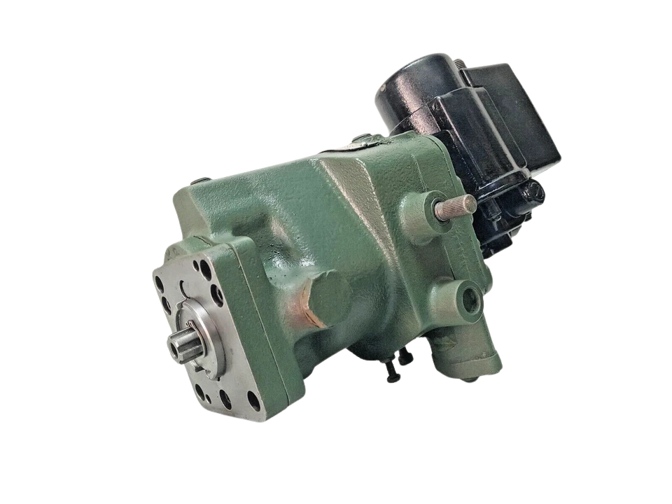




Woodward Governor Part No. 8511 211 with Synchronizing Motor
The Woodward Governor Part No. 8511 211 with Motor (UG-8 Series architecture) is an industrial-grade, mechanical-hydraulic governor engineered for precise isochronous or droop speed governing of marine propulsion diesel engines, auxiliary generator sets, and industrial prime movers.
The 8511 211 enables seamless remote frequency matching, switchboard generator synchronizing, and proportional load sharing from engine control rooms (ECR) or integrated power management systems (PMS). Featuring a self-contained 1.9-liter hydraulic sump, bidirectional internal gear pump, dashpot pressure compensation, and an 8 ft-lb (10.8 N·m) rotary terminal shaft output, this unit delivers exceptional stability, anti-hunting regulation, and fail-safe prime mover protection under severe transient loads.
Technical Details
| Specification Parameter | Rated Value / Engineering Standard |
|---|---|
| Manufacturer & Part Number | Woodward Inc. / MPN: 8511 211 (8511-211) |
| Governor Type & Operating Mode | Mechanical-Hydraulic Isochronous / Speed Droop Governing |
| Synchronizing Motor Input Rating | 24V DC / 110V-115V AC/DC Reversible Universal Motor (Configured per build tag) |
| Motor Duty Cycle & Limits | Intermittent rating; built-in slip clutch & internal micro-switches for mechanical limit protection |
| Output Terminal Shaft | 12.70 mm (0.500 in) diameter, SAE-36 serrations (double/single-ended output) |
| Terminal Shaft Angular Travel | 42° total stroke (28° to 30° recommended effective operating travel) |
| Maximum Work Capacity | 8.0 ft-lbs (10.8 N·m) maximum peak; 5.3 ft-lbs (7.2 N·m) continuous useful work |
| Drive Speed Range | 375 RPM to 1500 RPM (Recommended continuous operating range: 1000 to 1500 RPM) |
| Drive Shaft Connection | Standard 5/8″-36 serrated spline shaft (Optional: keyed taper shaft configuration) |
| Drive Power Requirement | Approximately 249 Watts (0.33 HP) at operating temperature and rated speed |
| Drive Rotation | Clockwise (CW) or Counterclockwise (CCW); internal 4-check-valve automatic directional routing |
| Steady-State Speed Band | ±0.25% of continuous rated speed under stable operating conditions |
| Droop Adjustment Range | Externally adjustable from 0% (true isochronous) to 12.5% at 1500 RPM (up to 19% at 1000 RPM) |
| Hydraulic Operating Pressure | 758 to 827 kPa (110 to 120 PSI) regulated via internal accumulator/relief piston system |
| Fluid Capacity & Type | 1.9 Liters (2.0 US Quarts) self-contained sump; SAE 10W to SAE 40W (100–300 SUS at operating temp) |
| Operating Ambient Range | -29°C to +93°C (-20°F to +200°F) continuous hydraulic oil operating limit |
| Housing Material & Mounting | Heavy-duty cast iron body; vertical or up to 45° tilt mount; (4) 5/16″-18 base mounting studs |
| Net Weight | 23.0 kg (50.7 lbs) including integrated electric speed-adjusting motor assembly |
Terminal Allocations & Wiring Schematic
- Terminal 1 (Raise / Faster): Positive line for clockwise motor rotation (advances speeder spring tension to increase fuel delivery/frequency).
- Terminal 2 (Lower / Slower): Positive line for counter-clockwise motor rotation (relaxes speeder spring tension to reduce fuel delivery/frequency).
- Terminal 3 (Common / Neutral): Power common return path for DC split-field circuits or AC neutral line.
- Terminal 4 (Protective Earth / Chassis Ground): Ground terminal bonded to the governor housing.
- Auxiliary Limit Micro-Switches (Internal): Wired in series with Raise/Lower poles to prevent motor overrun and gearbox stripping when the synchronizer knob reaches travel stops (Min/Max stop index).
Prime Mover & Equipment Compatibility
- Marine Auxiliary Diesel Generator Sets:
- Wärtsilä / Sulzer: S20, AL20/24, AL25 series
- MAN B&W / Holeby: 23/30, 28/32, L16/24, L21/31, L27/38 auxiliary gensets
- Daihatsu: DL-20, DK-20, DE-18, DS-22 series
- Yanmar: S165, M200, N21, EY18, EY22 diesel units
- Caterpillar / MaK: MaK M20, M25, Cat 3500 and 3600 generator arrangements
- Bergen / Rolls-Royce: K-series auxiliary packages
- Steam Turbines & Pumping Applications:
- Direct mechanical or rod-linkage throttle valve control on industrial/marine boiler feed pump turbines, lube oil pump turbines, and cargo oil pumps (COPT).
- Cross-Model Mounting Interchangeability:
- Compatible with standard UG-8 base plates, drive hubs, and mounting flanges conforming to Woodward 4-bolt patterns.
Part Number Cross-References
- Woodward Part Number: 8511 211 / 8511-211
- Related UG-8 Series Models: 8520-289, 8527-010, A8522-807, 8521-076, 8522-807
- Standard UG-8 Dial with Synchronizer Part Grouping: 8511-Series, 8520-Series, 8522-Series
- Interchangeable Actuator / Governor Replacements: Woodward UG-8D (Dial), UG-10D, and compatible electronic retrofits (e.g., Woodward UG40-DI or PGA series retrofits where 8 ft-lb stroke matches).
Frequently Asked Questions
What is the primary function of the Woodward 8511 211 governor?
The Woodward 8511 211 is a mechanical-hydraulic governor that senses prime mover shaft RPM and modulates the engine fuel rack via an 8 ft-lb hydraulic output shaft. The built-in electric motor allows remote speed and frequency trimming from switchboards or vessel power management systems (PMS).
Can the Woodward 8511 211 operate in both clockwise and counter-clockwise rotation?
Yes. The governor base incorporates an internal four-check-valve hydraulic circuit. Regardless of whether the drive shaft rotates clockwise (CW) or counter-clockwise (CCW), oil from the internal sump is always routed into the accumulator system under proper working pressure.
How do I eliminate governor hunting (speed oscillation) after installation?
Speed hunting is usually caused by an improperly tuned dashpot needle valve or aerated oil. Back out the needle valve slightly, allow the internal circuit to purge any trapped air through the compensation cylinder, and re-tighten the needle valve gradually until speed steadies. Verify that oil level is halfway on the sight glass.
What is the difference between Isochronous and Droop mode on this model?
In Isochronous mode (0% droop), the governor maintains constant engine speed regardless of electrical load. In Droop mode (1% to 12.5%), engine speed slightly declines as load increases, allowing multiple generators connected to the same busbar to share load proportionately without power swinging.
What voltage is required for the speed synchronizing motor on part 8511 211?
The synchronizing motor on the 8511 211 is typically delivered in either a 24V DC split-field configuration or a 110V/115V AC/DC universal rating depending on vessel switchboard architecture. Always cross-check the stamped voltage rating on the motor housing nameplate prior to energizing.