


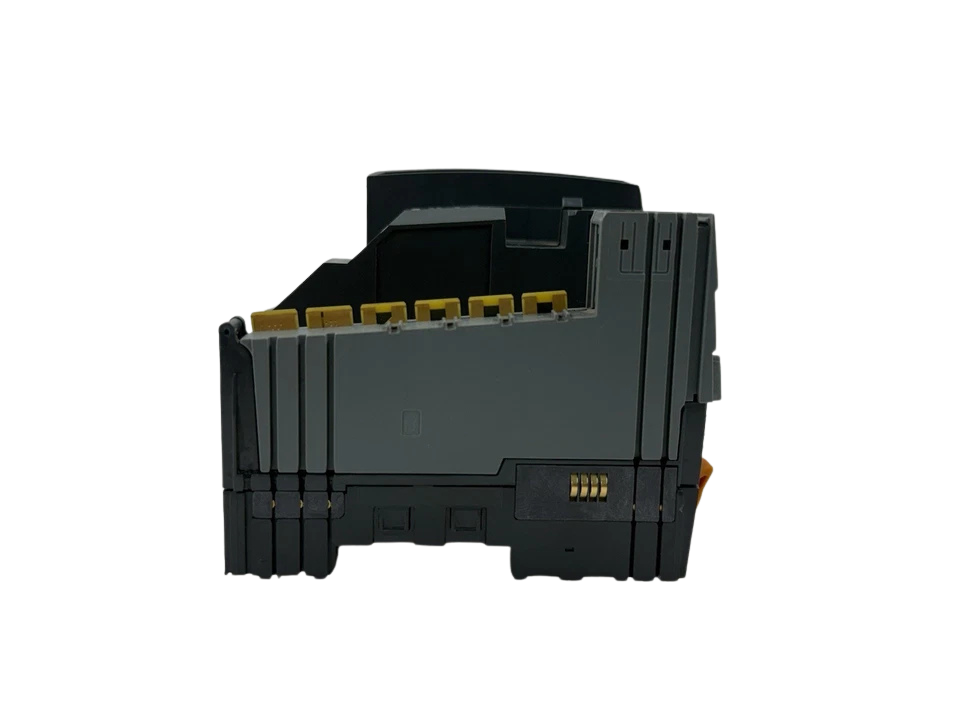
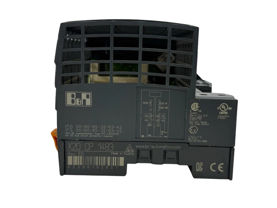
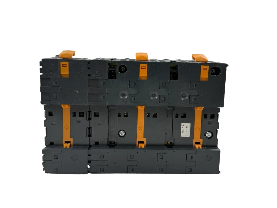
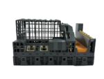
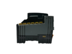
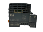


B&R Automation X20CP1483 PLC Processor Module
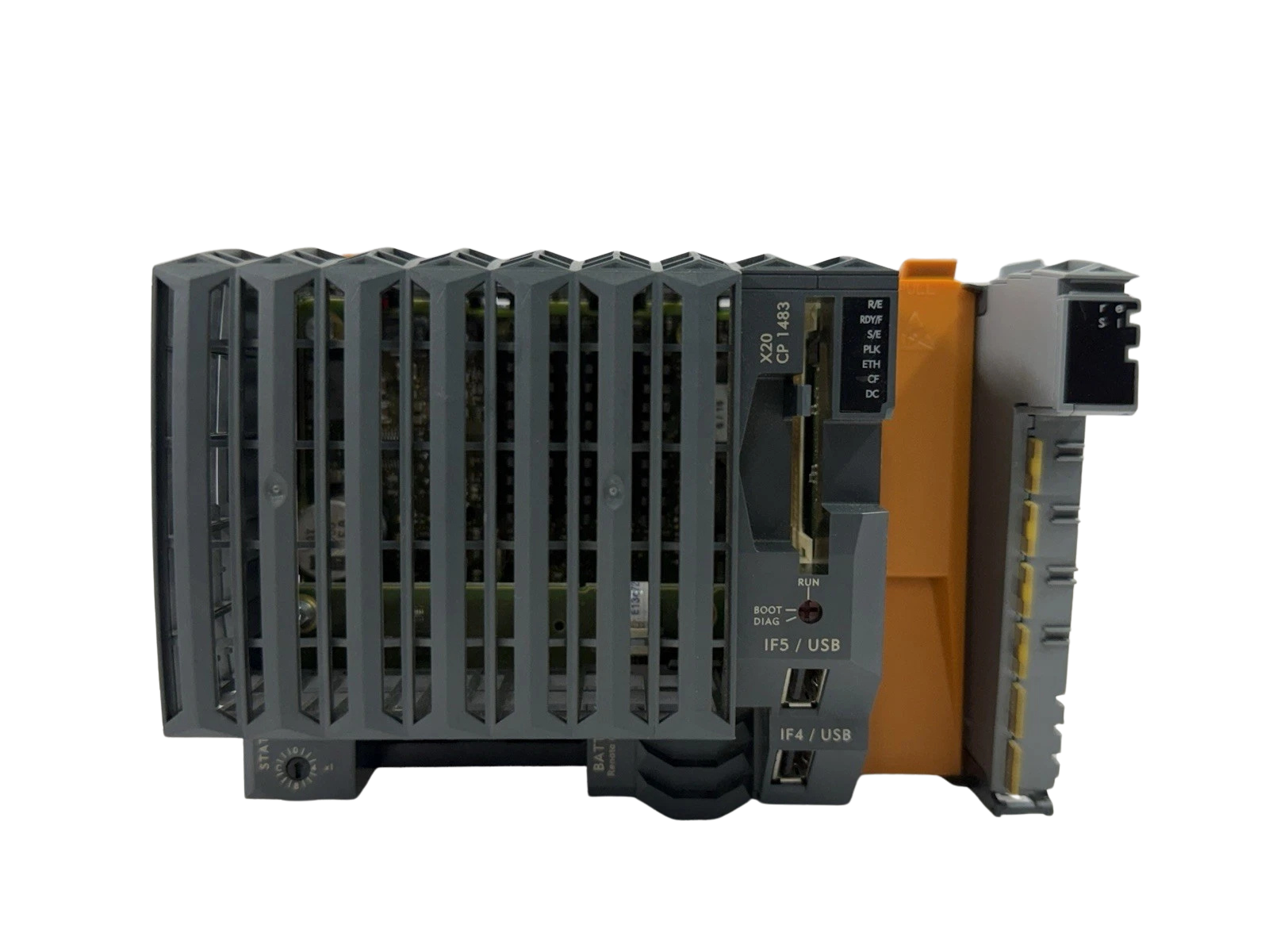
The B&R Automation X20CP1483 is a central processing unit within the modular B&R X20 control architecture. Driven by an x86 100 MHz-compatible computing core alongside a dedicated coprocessor for background I/O cycle execution, the X20CP1483 delivers deterministic task execution down to 1 ms. It integrates fieldbus connectivity on board—featuring Ethernet (10/100 Mbit/s), real-time Ethernet POWERLINK (V1/V2 configurable as managing or controlled node), dual USB ports, and a software-configurable RS232 serial link on the primary supply terminal.
The modular construction integrates a built-in power supply slice with X2X Link backplane generation, supplying up to 7.0 W of dedicated bus power directly to connected base modules and slice cards. Certified under rigorous marine classification society standards—including DNV, Lloyd’s Register (LR), American Bureau of Shipping (ABS), and Bureau Veritas (BV)—the X20CP1483 provides operational resilience against electrical fast transients, high-amplitude vibration (4 g), and corrosive thermal variations typical of marine switchboards, deck equipment, engine rooms, and automated industrial machinery.
Model Details
- Manufacturer: B&R Industrial Automation GmbH
- Model: X20CP1483
- Manufacturing Part Number (MPN): X20CP1483
- B&R Hardware ID Code: 0xA239
- Included Terminal Block: X20TB12 (12-pin spring-clamp terminal block, 24V coding)
- Included Bus Terminator / Plate: X20AC0SR1 (Right-hand locking/bus termination cover plate)
Technical Details
| Parameter / Subsystem | Engineering Value / Specification |
|---|---|
| Processing Core | x86-compatible 100 MHz CPU with integrated FPU + dedicated background I/O coprocessor |
| Instruction Performance | Typical instruction cycle time: 0.09 μs; Shortest task class cycle: 1 ms |
| Internal Memory (RAM / Retentive) | 32 MB SDRAM system memory; 128 kB SRAM user memory; Up to 32 kB remanent retain memory |
| Application & Removable Memory | 1x CompactFlash (Type I) interface slot (Firmware / Runtime / Project Data via B&R CF cards) |
| Real-Time Clock (RTC) | Integrated nonvolatile RTC; 1 s resolution; Accuracy: -10 to +10 ppm at 25°C; Lithium coin cell backed |
| Nominal Supply Input Voltage | 24 VDC nominal (-15% / +20% tolerance: 20.4 VDC to 28.8 VDC) |
| Max Supply Input Current | 2.2 A max at 24 VDC (inclusive of full slice bus and output drive draw) |
| CPU Power Dissipation | 6.0 W base (without memory card, interface modules, and USB peripherals attached) |
| X2X Link Output Bus Power | 7.0 W nominal; Supports parallel operation with downstream supply modules (75% rated load rating) |
| Internal Protection | Integrated reverse polarity protection; Integrated internal fuse (non-replaceable solid-state safety link) |
| Field Power Supply Terminals | 24 VDC I/O supply pass-through: Max continuous bus bar rating 10 A (requires external 10 A slow-blow fuse) |
| Interface IF1 (Serial Port) | RS232 (RXD, TXD, RTS, CTS, GND); routed through 12-pin X20TB12 terminal block; Up to 115.2 kbit/s |
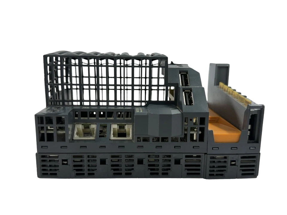
| Interface IF2 (Ethernet) | 1x RJ45 shielded port; 10BASE-T / 100BASE-TX (10/100 Mbit/s); Full/Half duplex; Auto-MDI/MDIX |
| Interface IF3 (POWERLINK) | 1x RJ45 shielded port; 100BASE-TX (100 Mbit/s); Managing Node (MN) or Controlled Node (CN); Configurable Ethernet fallback |
| Interfaces IF4 & IF5 (USB) | 2x USB 1.1 Type-A host sockets; Max continuous output current: 0.5 A per channel |
| Interface IF6 (Backplane Fieldbus) | X2X Link direct master bus backplane connection (slice-to-slice sliding base bus) |
| Modular Expansion | 1x free slot for X20 interface module (e.g., X20IF1041-1, X20IF1043, X20IF1051, X20IF1061) |
| Terminal Connection Block | 12-pin spring-clamp connector (X20TB12); Conductor cross-section: 0.08 to 1.5 mm² (28 to 16 AWG) |
| Status Diagnostic LEDs | r/e (Run/Error CPU state), S/E (POWERLINK state/error), ETH (Link/Act), CF (Access), BATT (Low battery) |
| Operating Temperature | Horizontal DIN-rail mounting: -25°C to +60°C; Vertical mounting: -25°C to +50°C |
| Storage / Transport Temperature | -40°C to +85°C |
| Permissible Relative Humidity | 5% to 95%, non-condensing (Storage & Operation) |
| Operating Altitude & Derating | 0 to 2000 m: No derating; >2000 m: Reduce max ambient temperature by 0.5°C per 100 m elevation |
| Ingress Protection Rating | IP20 according to EN 60529 / IEC 60529 |
| Vibration & Shock Mechanical Load | Vibration: 4 g steady test (marine bridge/engine rating); Shock: 30 g, 11 ms half-sine pulse |
| Physical Dimensions & Weight | Width: 150.0 mm; Height: 99.0 mm; Depth: 85.0 mm; Weight: ~300 g |
Features
- High-Efficiency Dual-Core Computing Architecture: Combines an x86 100 MHz instruction core with an autonomous background I/O processor and floating-point unit (FPU) for microsecond instruction execution and cycle times down to 1 ms.
- Native Industrial & Real-Time Ethernet: Standard RJ45 Ethernet (10/100BASE-TX) combined with a dedicated hardware POWERLINK interface (V1/V2, 100BASE-TX) for deterministic motion control and sub-millisecond network synchronization.
- Integrated System Power Supply & Bus Driver: Onboard power conditioning feeds both internal CPU logic and provides 7.0 W of isolated 24 VDC / 5 VDC bus drive via the proprietary X2X Link backplane.
- Rugged Fanless Mechanical Construction: Heat-dissipating solid-state housing rated IP20 with 4 g vibration endurance, 5% to 95% relative humidity tolerance, and -25°C to +60°C operating thermal window.
- Modular Interface Expansion: Includes 1 multipurpose communication slot compatible with B&R X20 interface cards (CAN bus, RS485/422, Profibus-DP, LIN, and dedicated master boards).
Compatibility
- I/O Slice Compatibility: Compatible with all standard B&R X20 Series digital modules (e.g., X20DI9371, X20DO9322), analog modules (X20AI4622, X20AO4622), counter slices, RTD/thermocouple temperature modules, and power supply feed slices (X20PS9400).
- Interface Slot Compatibility: Accepts single-width X20 communication add-ons, including:
- X20IF1041-1 (CAN bus Master/Slave interface)
- X20IF1043 / X20IF1043-1 (RS485 / RS422 serial line)
- X20IF1051 (Profibus DP Slave interface module)
- X20IF1061 (Dedicated device interface controller)
- Storage Cards: Requires B&R industrial-grade CompactFlash cards formatted with Automation Runtime (e.g., 0CFCRD.0128E.01, 0CFCRD.0512E.01, 0CFCRD.2048E.01).
- Motion Integration: Direct, deterministic synchronization with B&R ACOPOS and ACOPOSmicro servo drives via the onboard real-time POWERLINK interface.
Frequently Asked Questions
Can the B&R X20CP1483 be used to replace an X20CP1484 or X20CP1485 module?
The X20CP1483 shares the exact physical footprint, 12-pin connector layout, and pin assignments with the higher-frequency CPUs (X20CP1484, X20CP1485, and X20CP1486). However, the X20CP1483 operates an x86 core clocked at 100 MHz with 32 MB SDRAM. It is suitable as an exact drop-in replacement if your Automation Studio project runtime and task class cycles do not exceed the memory and compute capacity of the 100 MHz / 32 MB architecture.
What is the difference between X20CP1483 and X20CP1483-1?
The standard X20CP1483 is equipped with 32 MB SDRAM system memory, whereas the upgraded X20CP1483-1 provides 64 MB SDRAM. All other specifications—including processor speed (100 MHz), port allocations, supply ratings, and dimensions—are identical.
Why are multiple red LEDs blinking when I first power on the module?
A brief series of flashing red status LEDs immediately following 24 VDC power-up is standard internal hardware initialization and memory self-testing. If the LED pattern clears and the r/e LED transitions to solid green, the system has successfully booted into operational mode. A persisting blinking code indicates missing CompactFlash media, unconfigured firmware, or a bus line fault.
Does the X20CP1483 require an external CompactFlash card to run?
Yes. The operating system (Automation Runtime), project application code, and initial configuration are loaded from an approved B&R industrial CompactFlash card inserted into the onboard front slot. The module cannot boot to standard RUN mode without a valid, configured CF memory card.
How do I configure the RS232 serial interface on the X20CP1483?
The RS232 port is accessed via pins 3, 4, 5, 8, and 9 of the 12-pin terminal block X20TB12 (Interface IF1). Communication parameters—including baud rate (up to 115.2 kbit/s), parity, and flow control—are mapped directly within B&R Automation Studio hardware configuration and handled through native serial libraries.